Reading a multimeter spec: true-RMS and CAT ratings
Two specifications decide whether a meter reads correctly and whether it is safe on the circuit in front of you. Neither is the headline number on the box.
Multimeter listings lead with the numbers that are easy to compare — maximum voltage, count, number of functions. The two specifications that decide whether the instrument reads correctly and whether it is safe to use are usually further down the page.
True-RMS versus averaging
An AC voltage reading is a single number describing a waveform that is constantly changing. RMS — root mean square — is the number that corresponds to the equivalent DC voltage in terms of heating power, which is what you almost always want.
Cheaper meters do not measure RMS. They measure the average rectified value and multiply by a fixed constant, roughly 1.11, which produces the correct RMS figure for a clean sine wave and nothing else. On mains voltage from the utility, feeding a resistive load, that assumption holds and an averaging meter reads accurately.
The assumption breaks the moment the waveform is not sinusoidal. Variable-frequency drives, LED lighting, switch-mode power supplies, dimmers, inverters, UPS output, electronic ballasts — all distort the waveform. On those, an averaging meter can read low by 10% or more, occasionally much more. The reading looks entirely plausible. That is what makes it dangerous: you are not warned, you are just wrong.
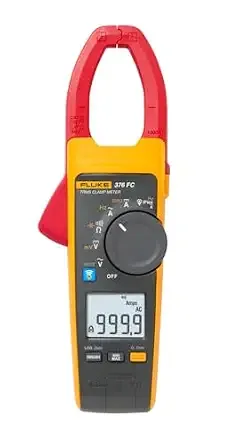
A true-RMS meter computes the actual RMS value and stays accurate regardless of waveform shape. If you work on anything built after about 1990, this is the specification to insist on. A clamp meter like the Fluke 376 FC is true-RMS on both voltage and current, which matters as much for current as it does for voltage — motor and drive currents are often badly distorted.
One caveat worth knowing: true-RMS meters specify a crest factor limit, typically around 3:1. Loads with very peaky current draw can exceed it, and the meter will under-read at the top of its range. It is rarely a problem outside specialised work, but it is why the spec exists.
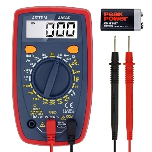
An averaging meter is not useless. For continuity, DC, resistance, and sine-wave mains it is fine, and something like the AM33D is a sensible thing to keep in a drawer. Just know what it cannot tell you.
CAT ratings are a safety spec, not a range
This is the specification most often misread, and the one that can injure you.
A CAT rating does not describe how much voltage the meter can measure. It describes how much transient energy the meter can absorb without the fault reaching your hands. Power distribution systems carry voltage spikes — from switching, lightning, motor starts — and the closer you are to the supply transformer, the more energy is behind them, because there is less circuit impedance to damp the surge.
The categories map to that distance:
- CAT I — electronics not connected to mains: battery circuits, signal level.
- CAT II — appliances and receptacle-connected loads. A plugged-in device.
- CAT III — fixed installation: distribution boards, feeders, hard-wired motors, industrial equipment.
- CAT IV — the origin of the installation: service entrance, meters, outdoor supply conductors.
The critical point is that the category matters more than the voltage number. A CAT III 600 V meter is built for a more severe transient environment than a CAT II 1000 V meter, despite the lower headline figure. If you are working at a panel, the category is what protects you, and the voltage rating alone tells you nothing about that.
Two things to check beyond the rating itself. First, look for independent certification — a mark from UL, TÜV, CSA, Intertek or similar. A printed "CAT III 600V" on the case is a claim; a listing mark means somebody tested it. Uncertified meters carrying impressive category markings are common and are exactly the ones you do not want at a distribution board.
Second, the rating applies to the whole measurement chain. Leads and probes carry their own category rating, and the assembly is only as good as its weakest part. Fitting CAT II leads to a CAT IV meter gives you a CAT II instrument. Check the leads, check the probe tips, and replace leads with cracked insulation rather than taping them.
Counts, resolution and the extras that matter
Count is the largest number the display can show — a 2000-count meter reads to 1999, a 6000-count meter to 5999. It sets resolution, not accuracy. A 6000-count meter can display 1 mV steps at the 6 V range where a 2000-count meter shows 10 mV steps.
Accuracy is quoted separately and is the specification that tells you whether the reading is true, usually as ±(percentage of reading + number of digits). More counts on a poorly specified meter buys you extra decimal places of a wrong answer. Read both figures together, and note that accuracy is usually quoted for DC volts — AC and current accuracy are typically looser, and are listed further down.
Beyond the headline numbers, the features that genuinely change day-to-day work:
- Low-impedance (LoZ) mode loads the circuit slightly to dissipate ghost voltages induced on unconnected conductors. Without it you get phantom readings on long runs and spend an afternoon chasing a fault that is not there.
- Min/Max and peak capture catches inrush and intermittent events you cannot watch for by eye.
- A flexible current probe gets around cable bundles and busbars a rigid jaw will not fit. The iFlex-style coil on the 376 FC is the reason many people choose that meter over a cheaper clamp.
- Wireless logging lets you leave the meter connected in an enclosure and read it from outside — safer, and it makes intermittent faults tractable.
- A good continuity beeper that responds quickly matters more than any spec on the page if you spend your day ringing out cables.
When a scope beats a meter
A multimeter reduces a signal to one number per reading. That is the right answer for steady-state values and the wrong one for anything that changes shape, because the meter cannot show you why a reading is odd.
Reach for an oscilloscope when the question is about timing, shape or noise: switching supply ripple, PWM duty cycle, communication bus activity, a relay that chatters, an intermittent glitch too brief for a meter's sampling to catch. Those are questions about a waveform, and only a waveform display answers them.
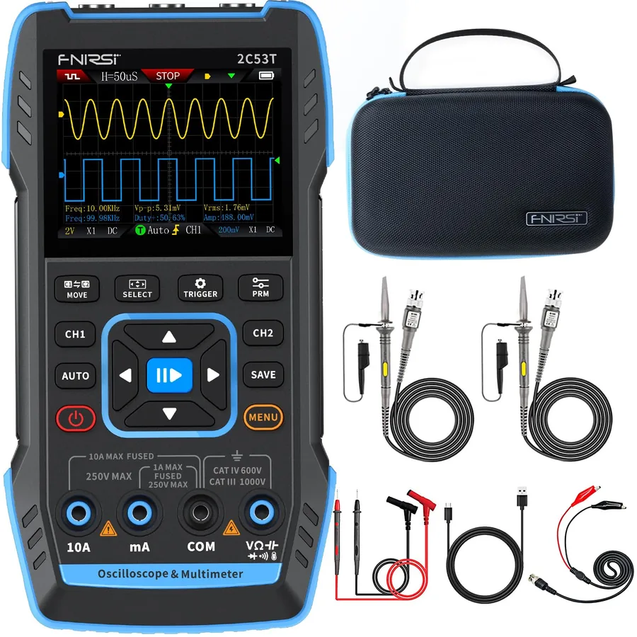
Handheld combination instruments have made this a much smaller step than it used to be. A pocket unit like the 2C53T puts a basic two-channel scope, a meter and a signal generator in one tool. It will not replace a bench scope for serious design work — bandwidth and sample depth are limited, and the screen is small — but for field diagnosis it answers questions a meter simply cannot.
The practical rule: a meter tells you the value, a scope tells you the story. If the value looks right and the circuit still misbehaves, you want the story.
If you are choosing between two instruments and cannot separate them on the datasheets, call us. We would rather spend ten minutes on the phone than have you buy the wrong category of tool.